Açıklama
Cihazla bilgisayar arasında iletişim izleme yazılımı ile iletişimin kesilmesi durumunda 4000 adede kadar olayı dahili hafızaya kaydedebilme, Ademco Contact ID protokolü, bilgisayara RS232 portu ile bağlantı, kesintisiz çalışma için yedek pil bağlama imkanı, 12 VDC
Quick Guide
FW ver: 0.7.12
(12-08-2004)
http://cdrs.try.hu
DRC2 Quick Guide page 1
Main Features:
• 2 independent Linecards
• External (Wall-mounted) DC12V power unit or 12V UPS
• In-built 6V battery charger with programmable charging current (6V -1.3Ah, 4Ah, 7Ah)
• No interference signal transmission and the in-built 6V power supply provides effective linear stabilizators.
• Low power consumption, long life battery. (more than 30 hours with 6V-4Ah)
• In-built Clock. (Y2K compatibility).
• In-built Event Buffer (max: 4000 events)
• In-built parallel printer output (printer event buffer)
• Programmable printing modes
• Standard serial protocol (Basic + Clock signal)
• Serial line for parameter setting and FW Update
• Multilink (in versions 1.0.11 or higher)
• In-built sounder with tones and programable function modes
• In-built Acknowledge button.
• Clear, multicolor LEDs for particular functions
• Programmable (OC) output for essential troubles.
• Programmable input (external anti-tamper or external acknowledgement)
• Small design, easy installation
Recommended application:
This low-cost device is ideal for smaller systems but with linked receivers it can be used in municipal monitoring
as well.
• Backup system Stations
• Building Monitoring Stations
• Technical Monitoring Stations
• Municipal Monitoring Stations
DRC2 Quick Guide page 2
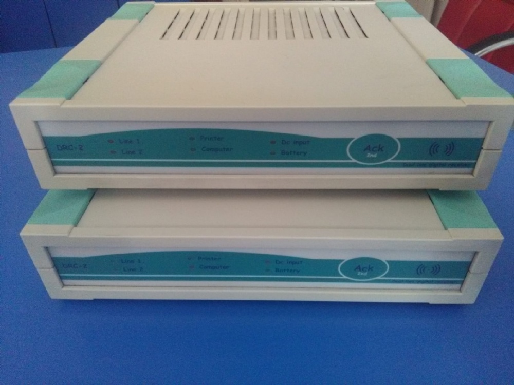
Front
Internal Sounder:
The internal sounder can be programmed different functionsi:
• Always Off
• Always On
• Enabled in „offline” only.
If the sounder is enabled a short sound can be programmed to notify line events (if the reception is incorrect two
long signals will be heard).
The meaning of the sounds:
• Short, high sound: Button pressed or new line event
• Two deeper sounds: System failure (flashing red LED(s)) repeated until acknowledged or wrong line
format.
• Deep sound in every minutes: Internal clock not set
If the sounder is enabled new troubles will appear with flashing red light. After manual acknowledgement, red
lights will turn to steady and the sounder will go off.
Acknowledge button:
It is a multi-function button:
• Short press means acknowledgement.
• After 2 second hold, short repeated (every 1sec) sounds indicate function menu scrolling. After the 8th
sound release the button and the receiver resets
Line Status:
Green:
- Line OK
Flashing Green:
- On-line
Orange:
- On-line reception
Red:
- Line Trouble Printer Status:
Green:
- Printer OK
Red:
- Printer not ready or no
paper
RS232 status:
Green:
- Connection OK
Orange:
- Waits for Ack.
Red:
- Connection lost
6V Battery Status:
Green:
- Battery voltage OK
Orange:
- Charging
Red:
- Low Battery
DC12V Input
Status
Green:
- Voltage OK
Red:
- Low Voltage
Ack. button
Short:
-
Acknowledgement
Long (8 beeps):
- Receiver Reset
DRC2 Quick Guide page 3
Backplate Connectors
DC input
Connector for external 12VDC. The required input voltage is 11 – 20V. The receiver reports trouble if the
voltage drops below 11Volts. Supply adequate charging current for the battery.
Maximum current consumption (when charging) in accordance with the battery settings:
1.3Ah 70 - 250mA (Wall-mounted power supply e.g. ICA12-500PC)
4Ah 70 - 500mA
7Ah 70 - 900mA
The input is polarity-proof. If the polarity is reversed the power supply won’t be recognised.
6V Battery
6V battery can be connected only!!!
Do not connect external load to the battery clamps since it affects the function of the automatic charger!
The battery input is polarity-proof and short protected (electrical). The recewiver will shut down an case of
abnormal state.
By default, the charger operates in longer charging time (charging current is 5-10% of the capacity) to spare the
battery lifetime. The charging current can be decreased but it is not recommended to set it to a higher value.
PGM input
The programmable input recognises the closing of PGM In to GND terminal. In Anti-Tamper input function, the
cut (NC) causes alarm and the short causes restoral.
Printer output
6V Battery connector
(1.3Ah, 4Ah, 7Ah)
PGM input
- external ACK
button
- Tamper input
Alarm (NC),
Restore(NO)
PGM output
- Output with open
collector with 100mA
capacity.
DC 12V Input
- Wall-mounted power
supply or external
power supply.
RS232 Serial Input
- Parameter setting
- Event donwload
- FW update
Data connection with
other receivers
Earth
(1-2 line)
Line Input (1,2)
- Telephone line
- Radio Receiver
DRC2 Quick Guide page 4
PGM output
PGM output is an open collector output with 100mA loads capacity. It supplies steady negative (GND) until the
programmed troubles are present. It can supply small sounder, strobelight or relay spool. It can’t supply positive
to the connected unit! Use the positive of the 12V input (Do not use the positive of the battery!).
Serial
RS232 input and output for PC connection. In the following format:
9600 baud, 7bit + Even parity, 1 stop bit
Printer
Parellel printer outpu (40 or 80 characters/line). Programmeble printer functions. In power on mode the system
continuously monitors the printer. The required minimum control signals for printer:
• STROBE Input
• DATA1-8 Inputs
• ACKNLG Output
• BUSY Output
• PE Output
• ERROR Output
Datalink
In- and Outputs for linking more receivers. (Not supported by the current version)
Line 1,2
Terminals of the Line Inputs are installed directly into the linecards therefore, it is always corresponds to the
current card. Telephone line connectors can be connected as in usual. (the inner two wires are the lines)
Earth
Lightning protection earth. It is the outlet of the lightning protection earth of the linecards. (The points are the
same inside therefore it is enough to use one of them). With this earth connection the efficiency of the
overvoltages can be essentially increased.
DRC2 Quick Guide page 5
Setup
1. Connect the end of the wire of the included wall-mounted power supply to the DC In input, do not apply
power yet.
2. Connect the plug of the included (9/9) serial cable to the receiver and the socket to the PC. The PC
connection is significant for the clock settings.
3. Connect the printer and switch it on. Optional.
4. Connect the included battery cable to the receiver (5-pole plug), do not connect the clamps to the battery yet.
The 6V battery is optional but supply 12V Ups if not used.
5. Connect the telephone line to the linecard (Line 1 orgy Line 2)
6. Connect the power supply to the Mains.
7. All LED in the frontplate light in orange, after 2 seconds the system starts.
8. „Line 1,2” lights in Green to indicate installed lines. If there is no card the LEDs are Off.
9. The „Printer” LED of the printer lights in Green (if the printer is enabled). If the printer is disabled the LED
is Off. The printer test takes 1 minute hence the green LED lights for a minute although there is no printer
connected.
10. The „Computer” LED lights in oreange (It is up to send reports to the PC but no acknowledgement arrives).
After 10 seconds, the flashibg red LED and the repeated sound warns that the connection to PC is lost. If the
monitoring program is running the LED lights in green after initialising the connection.
11. The „DC Input” LED lights in green indicating the adequate voltage of the 12V input.
12. The „Battery” LED of the 6V battery lights in green. Connect the clamps to the 6V battery (verify correct
polarity: Red – Positive, Black - Negative). If the battery takes charging current the LED goes green. The
default type of the battery is 1.3Ah (That is the maximum current the included power supply is able to
supply with the nominal voltage)
13. Stop occasional sound signals by the short press of the „ACK” button.
14. Run „DRCConfig” program on the PC then set the adequate parameters and time (Time can be set from
?rMe program).
15. Exit the program and start monitoring software (Set the serial format to 9600, 7 + Even Parity if not the
?rMe software is used).
Now, the receiver is ready to receive line events.
The receiver reset will clear the event buffer and resets teh clock but the parameters will be stored. Linecard
parameters will be uploaded to linecard only after reset, consequently reset the receiver after each modification.
Other parameters will be validated immediatelly. In subsequent software versions won’t require this reset.
Printer Format
A monitoring software (e.g. ÖrME) is siutable to operate the receiver but the events can be displayed on a printer
as well. The events can be divided into two essential groups: Events, status changes (account code 0000, line
number 0) generated by the receiver and the evnts arrived via line.
System Events:
11:16:58-07/02 0000-D0 Reset
1. 11:16:58-07/02 Hours : Mins : Seconds – Day / Month
2. 0000-D0 Account (receiver) – Event Code
3. Reset Short name of system event
4. 01-0 Receiver number (always 01) – line number (in System always 0)
Basic protokoll (4/1 – 4/3):
19:22:44-07/02 1234-58 P(4/2) 01-1
1. 19:22:44-07/02 Hours : Mins : Seconds – Day / Month
2. 1234-58 Account – Event Code
DRC2 Quick Guide page 6
3. P(4/2) Line format Pulse 4/2 (P – Pulse, DT – DTMF)
4. 01-1 Receiver number (always 01) – Line number (1 or 2)
ContactID protokoll:
14:36:14-07/02 1234-E130 z002g01 01-1
1. 14:36:14-07/02 Hours : Mins : Seconds – Day / Month
2. 1234-E130 Account – Event Code
3. z002g01 z – zone number, g – group number
4. 01-1 Receiver number (always 01) – Line number (1 or 2)
Debug protokoll:
11:57:14-07/02 ?(2341816A2A1AAA) 01-1
1. 11:57:14-07/02 Hours : Mins : Seconds – Day / Month
2. ?(2341816A2A1AAA) ?(non-interpretable digits)
3. 01-1 Receiver number (always 01) – Line number (1 or 2)
DRC-2 System Events:
System events arrive with account code 0000.
Code Printed Event Description
D0 Reset RECEIVER RESET After power on (Receiver reset)
05 CommErr COMM ERROR PC connection lost
06 Comm Ok COMM OK PC connection restored
01 Prn Err PRINTER ERROR Printer is Off or out of paper
02 Prn Ok PRINTER OK Printer ready
15 DCinErr DC IN ERROR No 12V power
16 DCin Ok DC IN OK 12V power restored
03 BattErr BATTERY LOW 6V battery voltage low
04 Batt Ok BATTERY OK 6V battery charged
0C ChangeP PROGRAM ACCESS Parameters modified ( DRC2Config )
1B SetTime TIME / DATE SET Clock set
07 TampArm TAMPER ALARM DRC2 tamper input in alarm
08 TampRes TAMPER RESTORE DRC2 tamper restored
09 Man Ack MANUAL ACK Acknowledgement on DRC2 (only if trouble occurs
after alarm)
Line System Events: (Line1, Line2)
Code Printed Event Description
20 LineErr LINE ERROR Line Error
30 Line Ok LINE OK Line OK
F0 CardTrb LINE CARD FAIL Linecard connection failed
10 CallTrb FAULT DATA Fault data on line (non-interpretable format)
DEBUG protocol lists the data
DRC2 Quick Guide page 7
Program Versions:
The Firmware of DRC-2 receiver can be updated subsequently by the user by FW update function. This function
helps the user to insert new features to the system.
FW v0.5.12 (2002-05-27)
Warning! Version v0.5.12 resets all parameters to default at the first update (e.g. v04.12 -> v0.5.12) because of
the extended parametrs!!! Therefore, after downloading, re-define the parameters (ifthe system use other settings
than default).
New Features:
• Serial port format can be set.
Format: 8 databits, no (None) parity, 7 databits + Even parity, 7 databits + Odd parity
DRC2 Config program operation is not affected by the port settings!
• Inaccurate clock warning signal can be disabled.
Repairs:
• Repaired date management.
DRC2 Quick Guide page 8
Compatibility with other receivers:
DRC-2 receiver is able to cooperate with Enigma CPM module by this means it can be used as secondary
receiver or even backup. Enigma feed bar can supply DRC-2 receiver (Enigma 12V ?? DRC-2 DC input ) Since
the Enigma 12V feed bar is UPS the 6V battery of DRC-2 is also needless. The serial output of DRC-2 is
connected to the COM2 input of the CPM module causing CPM screen display the events. For cables required to
connect the devices please, contact manufacturer. Before starting the operating perform the following settings in
DRC-2 receiver.
Since the dating of events received on the serial input of Enigma managed by CPM module (excluding Clock
signal) the clock of DRC-2 is disregarded. If no printer is connected to DRC-2 the clock setting is useless. To
prevent missing setting signal the sound can be disabled.
DRC2 Quick Guide page 9
Automation Software Interface Definition
Normally, when an event is received, the receiver sends it in a message to the automation software with the
protocol assigned to the event format. After sending one message to the computer, the receiver waits for the
acknowledge from the automation software. The acknowledge message is a CTRL-F (06h) character. The
acknowledge must be received within a 3 seconds timeout period.
If no acknowledge is received, the DRC-2 will try to resend the event 3 more times. If all attempts fail, the
receiver generates a “Communication Error” event, and will keep it in the memory buffer and repeatedly try to
send the event until it succeeds. The CPM Unit can store up to 4095 events in its memory buffer if the
connection to the central station computer is broken.
If the receiver succeeds to send the event after a communication failure a “Communication Restored”
event will be recorded. After the communication channel is restored, the DRC-2 will send all pending
reportable events from its memory buffer to the computer. This method provides reliable and supervised
communication between the DRC-2 and the central station computer.
The COM1 port is also supervised with heart-beat signals (See Serial Protocols/Heartbeat protocol). The heartbeat
signals are used to test the communication channels between the receiver and the central station computer
when there is no reportable event in the memory buffer. It works that way, that the receiver sends so called heartbeat
signals to the computer in a programmed time and requires acknowledge for that. If the acknowledge is
missing for 3 consecutive times, it assumes that the computer is failed, and gives “ Communication Error”
message.
If the automation software is not compatible with heart-beat supervision, the heart-beat signals can also be turned
off by programming the heartbeat period to 0 in the receiver.
Serial Port Options
Port setting is 9600 baud, 7 databits, even parity.
Note: in all protocols ‘s’ means space (20h). The digits not in use are also reported as spaces.
Basic Signal Protocol
The Basic Signal Protocol is the mostly used protocol by the receiver. Receiver status events and the 3/1, 3/2,
4/1, 4/2, 4/3 (etc.) events received by the Line Cards and also the events received by the radio module are
forwarded to the CPM using this protocol. The protocol format is:
1RRLssssAAAAAAssGYYY[DC4]
Where:
1 Protocol ID
RR Receiver number
L Line Card ID – can be ‘1’ to ‘2‘ for line cards 1 – 2
AAAAAA Account number
G Area/Group number – in case of radio received event, the power of the received signal
YYY Event code
[DC4] Terminator, 014h
DRC2 Quick Guide page 10
Heart-beat Protocol (Supervisory Protocol)
This protocol is used to supervise the connection between the digital receiver and the computer. It is sent
periodically in a programmable time interval and the computer should positively acknowledge it for verification.
(default period is 30 seconds)
1RR0sssssssssss@ssss[DC4]
Where:
1 Protocol ID (Basic Signal)
RR Receiver number
@ Heart-beat signal
[DC4] Terminator, 014h
Contact ID Protocol
The Contact ID Protocol is used to send messages received in Contact ID format to the computer
5RRLs18AAAAQXXXYYZZZ[DC4]
Where:
5 Protocol ID
RR Receiver number
L Line Card ID – can be ‘1’ to ‘2‘ for line cards 1 – 2
AAAA Account number
Q Event Qualifier E – new event or open, R – restore or close, P – previous event
XXX Class and event code
YY Group/Area number
ZZZ Zone/User number
[DC4] Terminator, 014h
Debug Protocol
This protocol is used to transmit the Fault Data the Line Cards received.
9RRLddddddddddddddds[DC4]
Where:
9 Protocol ID
RR Receiver number
L Line Card ID – can be ‘1’ to ‘2‘ for line cards 1 – 2
ddd..dd Fault Data received
[DC4] Terminator, 014h
DRC2 Quick Guide page 11
Clock Signal Protocol
The Clock Signal Protocol is used to transmit time and date information together with the events. The Clock
Signal is inserted to the serial protocol before the terminator character. The sending of Clock Signal Protocol can
be enabled or disabled (See DRC-2 Options). The Clock Signal format is the following:
[Protocol]HH:MM:SS-dd/mm[DC4]
or, when reporting of the year of the event is selected:
[Protocol]HH:MM-dd/mm/yy[DC4]
Where:
[Protocol] Protocol normally sent by the receiver (as described above)
HH Hour
MM Minute
SS Second
Dd Day
Mm Month
Yy Year (optional, see Y2K issue)
[DC4] Terminator, 014h
Note, that for the Heart-beat Protocol the Clock Signal is not inserted, even if it is enabled with other protocols.